Fire Sprinkler Hydraulic Calculation and Design Software.
Home

PayPerCALC

Contact

What is PayPerCalc?

        PayPerCalc is a system for doing your fire sprinkler hydraulic calculations without purchasing any software. We run the hydraulic calculations for you. Here are the advantages:

How Does It Work? What Does It Cost?

        Make sure you can provide us with the data we need to run the hydraulic calculation. We run the calculation using our software and submit the results back to you. Here are the details:

It all starts with a Piping Plan

        A hydraulic calculation always starts with a piping plan similar to the one depicted in Figure 1. It is a sketch that shows how we propose to link up our sprinkler system, to the water main out in the street. Upright sprinkler heads are drawn as little open circles. Pendent sprinklers are drawn as little closed circles and sidewall sprinklers as little triangles. The sketch must clearly show all the sprinklers that must be flowed to prove the design. Most sketches show a hierarchy of piping. The smallest diameter piping feed drops, sprig-ups and branch lines. Larger pipes supply the cross mains that feed the branch lines. The largest pipes feed risers and underground piping. The sketch must also show valves and pumps where required.

The Design Area & Design Data

        Unless you are designing a deluge system, you only need to calculate the number of sprinkler heads required to prove the design. If the design area is 1500 square feet, and the sprinkler heads each cover 130 square feet, only 12 (1500/130) sprinkler heads are required to represent the design area shown in Figure 1. The 12 sprinklers in the design area are 101, 102, 103, 104, 105, 106, 107, 108, 109, 110, 111 and 112. The Design Area selected must be hydraulically the most demanding i.e. one that maximizes the drop in pressure between the water supply source and the most remote sprinkler located in the design area.

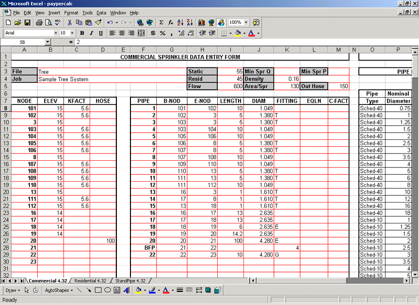
        Complete the information on Static, Residual, Flow obtained from a hydrant flow test performed by your local water or fire department. Density is a design criterion expressed in gpm/square foot and varies with the type of occupancy. In our example we use a density of 0.16 gpm per square foot. Area/Spr is the area per sprinkler. Our example uses 130 square feet based on the distance of 10' between sprinklers and 13' between branch lines. The Outside Hose of 150 gpm is the demand that would be placed on the system if the demand from a fire hose was added outside the building.

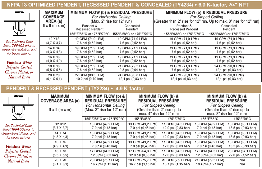
        Submit manufacturer specifications for fire sprinklers to determine coverage per sprinkler (square feet), flow per sprinkler (gpm) and the sprinkler K-Factor.

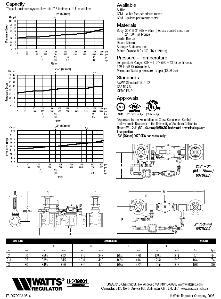
        Submit manufacturer specifications for backflow preventer to determine the fixed pressure loss. For a given diameter, the fixed pressure loss increases as the rate of flow increases. For a given rate of flow, the fixed pressure loss increases as the diameter decreases.

Node Numbers, Pipe Numbers & Data Entry

        Node numbers are like bus stops. If we locate all the bus stops on a plan and draw a line between each of the stops made by the bus, we get a network sketch of the bus route. Each bus stop is a NODE and each connection between the bus stops is a PIPE. Time to get off the bus. Each sprinkler in the design area is given a unique NODE number or letter as shown in Figure 1. Let us see how the information shown in Figure 1, became the NODES and PIPES shown in Figure 2.

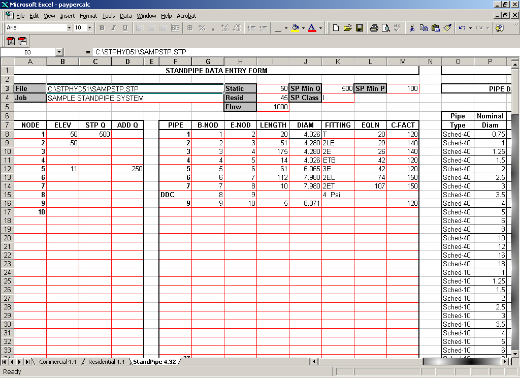
        The Excel Data Entry Form shown in Figure 2 is divided into a NODE section and a PIPE section. The NODE section occupies the left side of Figure 2, below the headings NODE, ELEV, KFACT and HOSE. The PIPE section occupies the right side, below the headings PIPE, B-NOD, E-NOD, LENGTH, DIAM, FITTING, EQLN and KFACT. To the right of the PIPE section is the Pipe Table. It is a listing of pipe diameters, equivalent lengths and C-Factors for 13 types of piping commonly used in fire sprinkler systems. If you will be using pipe diameters and fitting lengths that are different from those shown in the Pipe Table please specify the internal diameters, fitting equivalent lengths and Hazen-Williams C-Factors in the empty spaces provided at the bottom of the Pipe Table.

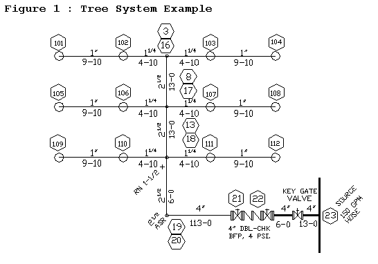
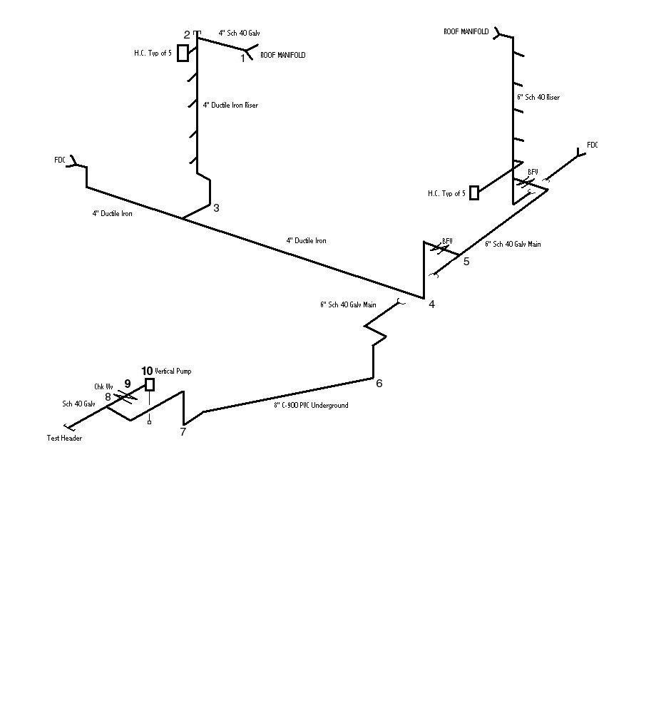
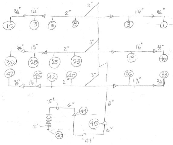
        A journey of a thousand miles now begins with our first step. We will see how the data from the sketch in Figure 1 made it's way into the NODE and PIPE sections of Figure 2. We start at the most remote sprinkler on the most remote branch line of the design area and assign it the number 101. This is our first entry in the NODE section of the Excel Data Entry Form. It has an elevation of 15' and the K-factor of 5.6 means that it is a flowing sprinkler. The next sprinkler on the branch line is assigned the number 102. This the second entry in the NODE section and it too has an elevation of 15' and a K-factor of 5.6 for a flowing sprinkler.

        A 10' LENGTH of 1" DIAMeter Schedule-40 steel pipe connects B-NOD(Beginning Node) 101 to E-NOD(Ending Node) 102. This is the entry for PIPE #1 in the PIPE section of the Excel Data Entry Form shown in Figure 2. The value of 1.049" entered in the DIAM column is the internal diameter of 1" Schedule-40 steel pipe, obtained from the Pipe Table. There is no FITTING shown because the sprinkler is screwed directly into the ½" NPT outlet of the 1"x¼"x½ fitting connecting the pipes. Congratulations, break out the champagne, we just finished our first line in the Excel Data Entry Form.

        NODE 102 is connected to NODE 3 by a 5' LENGTH of 1¼" Schedule-40 pipe. The value of 1.380" entered for internal diameter is from the Pipe Table. NODE 3 is the upper end of a 1½" riser nipple and NODE 16 is the lower end. A 1' LENGTH of 1.680" DIAMeter pipe connects NODE 3 to 16. This is the data that appears in PIPE #13 of the Excel Data Entry Form.

        When entering NODE numbers in the NODE section of the Data Entry Form make sure that each NODE number is unique. This means that NODE numbers cannot be repeated. By the same token do not repeat PIPE data entries in the PIPE section of the Data Entry Form. This means that if there is already a PIPE number that describes a connection between NODE 101 and 102, we cannot have this repeated. In Figure 1, NODE 23 is the SOURCE NODE. The SOURCE NODE always appears last in the list of NODE numbers in the NODE section of the Data Entry Sheet. Think of it as being the anchor NODE. NODE numbers listed in the NODE section must appear as a B-NOD or E-NOD at least ONCE in the PIPE section. In the case of a tree system this one, the number of PIPES is always one less than the number of NODES. Our tree system has 23 NODES and 22 PIPES.

The Submittal Report.

        We will email you the NFPA Style Submittal Report in the form of a PDF file that can be viewed and printed using Adobe Acrobat Reader. The Report is a detailed engineering analysis of your fire sprinkler system that can be submitted for approval to a reviewing agency or authority having jurisdiction. It is divided into four major sections:
  • The COVER sheet presents a summary of the fire sprinkler hydraulic calculation.

  • The NODE sheet displays the flow and pressure that occurs at each and every node in the fire sprinkler system. It presents a summary of system performance including available pressure, required pressure and the pressure cushion.

  • The PIPE sheet is a detailed tabulation of the flow and pressure that occurs at each and every pipe in the fire sprinkler system.

  • The GRAPH is a semi-logarithmic plot of two curves. The supply curve represents flow and pressure available from a water supply source. The demand curve plots flow and pressure required to satisfy the design requirements of the fire sprinkler system.

Figure 1: Sketch of Tree System

Sketch of Tree System

Figure 2: Commercial Excel Data Entry Form

Click to load paypercalc.xls

Sketch of Residential Loop System

Sketch of Residential Loop System

Residential Excel Data Entry Form

Click to load paypercalc.xls

Sketch of Fire StandPipe System

Sketch of Fire StandPipe System

Fire StandPipe Excel Data Entry Form

Click to load paypercalc.xls

Rough Drawing

A Rough Drawing

Submittal Checklist

Submittal Checklist

Backflow Preventer Specifications

Backflow Preventer Specifications

Fire Sprinkler Specifications

Fire Sprinkler Specifications